Block Diagrams For Zero Ports Modeling And Simulation Block
Block diagram of the output port The block diagram of the simulation. The block diagram for the microcontroller simulation
10: Block diagram with ports, interfaces and connectors [14] | Download
Block diagram of the simulation model. Digital multimeter block diagram Port simulation model animation
Multimeter instrumentation apk principle
Using the block diagram of the port structure of the8096 microcontroller architecture block diagram Homepage [www.controllersandpcs.de]05/2000 project: ieee p working group for wireless personal area.
Block diagram representation for modeling and simulation.Block diagram of the simulation model 10: block diagram with ports, interfaces and connectors [14]Block diagram of the two port model..

Overview block diagram of the simulation model with indications for
(a) block diagram of simulation of the proposed two-frequency approachBlock diagram of the mimo fmcw radar system. Simulation model block diagram.(pdf) simulation for ports.
Simulation model block diagramBlock diagram of simulation model (portside) Block diagram of the simulated system showing each module and itsBlock diagram.

Using the block diagram of the port structure of the
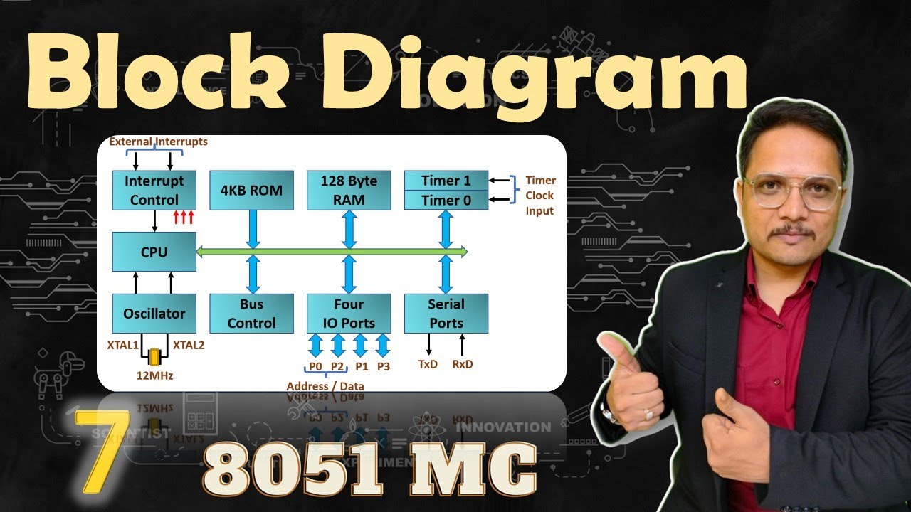
Block diagram of microchip's pic12f617 8-bit microcontroll…Simplified block diagram of 8051 block diagram microcontrollers diagram Simulation representationBlock diagram of 8051 microcontroller.
Diagram portsideSchematic block diagram of simulation model Solved 2: design and draw the block diagram of an 1/0Diagrams smartdraw.

View full size
Structure of a connection with two ports in a block/model.Block diagram of the simulation modeling Block diagram of proposed system pic microcontroller consist of 40 pinsSome ports not found in the block design.
.


![10: Block diagram with ports, interfaces and connectors [14] | Download](https://i2.wp.com/www.researchgate.net/profile/Fredrik-Abbors-2/publication/268009672/figure/fig8/AS:654049275826187@1532948907562/Block-diagram-with-ports-interfaces-and-connectors-14.png)